eli miten tämä homma toimii kun hajonaista tietoa löytyy kyllä mutta ei niistä ota selvää..
pitäis päästä flektiä ohjaamaan ms2extra v3.
tunerstudion kautta kyllä osaan sen laittaa pt6- pt7 (iac1-iac2) portteihin kun ei ole iac käytössä mutta miten siitä eteenpäin? tätä olen nyt aikani kattonu http://msextra.com/doc/ms2extra/MS2-Ext ... .htm#iouse tarviiko noi lähdöt levyn sisään jotain muutoksia vai pystyykö prossu ohjaamaan noilla lähdöillä suoraan relettä??
edit: http://www.extraefi.co.uk/Drawings/PDF_ ... ingfan.pdf
tässäkään ohjeessa ei puhuta mitään levylle tehtävistä muutoksista.
releen ohjauksesta?!
Moderator: Masi_K
Re: releen ohjauksesta?!
Onko sulla levyllä nämä jumpperit kytkettynä?
Connect (1A)JS0 (under the processor socket) to IAC1A (near the DB37 connector) - this brings out IAC1A on DB37 pin #25
Connect (2A)JS2 (under the processor socket) to IAC2A (near the DB37 connector) - this brings out IAC2A on DB37 pin #29
Connect (1A)JS0 (under the processor socket) to IAC1A (near the DB37 connector) - this brings out IAC1A on DB37 pin #25
Connect (2A)JS2 (under the processor socket) to IAC2A (near the DB37 connector) - this brings out IAC2A on DB37 pin #29
-
viagratabu
- Megasquirttaaja
- Posts: 69
- Joined: Sat Sep 25, 2010 15:20
Re: releen ohjauksesta?!
Tuolta löytyy: http://www.msextra.com/doc/ms2extra/build_manual.htm
"Solder components Q4, Q20 and R39 in place. Note, this gives you a programmable output that can drive a relay e.g. cooling fan on FIdle (Pin 30 of the db37)"
"Solder components Q4, Q20 and R39 in place. Note, this gives you a programmable output that can drive a relay e.g. cooling fan on FIdle (Pin 30 of the db37)"
-
--hartsa--
- Megasquirttaaja
- Posts: 44
- Joined: Wed Mar 21, 2012 15:26
Re: releen ohjauksesta?!
Jos tekee ohjauksen IAC1 ja IAC2 pinneistä niin tehäänkö se näin.

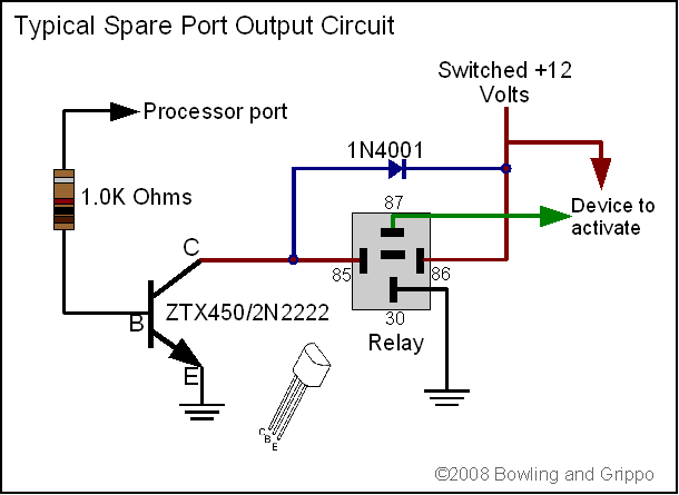
http://www.megamanual.com/ms2/SpareCircuit.gif
Elis vastus pistetään sinne haluttuun IAC1 tai IAC2 pinniin ja sitten loput tuon kaavion mukaan? miks tuossa on mainittu erikseen että 0-12volttia? Tahtosin noista vaihtovalolle lähdön/lähdöt niin pitää kysellä että onko jotain ihmeellistä noissa? Taisipa tohon alle löytyäkki tekstiä ku etsiskeli. Eli transistoria ei tarvita ku yhistää kaks johtoa neljästä. eli IAC1A ja IAC1B yhteen-> releen plussaksi..kö?
The following IAC outputs are capable of driving over 0.5 Amp directly, sufficient for most automotive relays. You can connect to them using the IAC pins on the DB37 (25, 27, 29, and 31). Also, note that IAC1A and IAC1B are inverted relative to each other, as are IAC2A and IAC2B.
IAC1 - PT6,
IAC2 - PT7.
Either IAC1A or IAC1B are 0-12V outputs. Requires jumper wire inside case. Can drive a relay
Either IAC2A or IAC2B are 0-12V outputs. Requires jumper wire inside case. Can drive a relay.
The two spare port "T" pins (PT6 and PT7) are normally used to drive the stepper motor chip (IAC1,2). When you set pin PT6 high, it will make 1 of the 4 stepper output pins high and the other low, and no effect on the last two - which are controlled in the same way by pin PT7. So, by picking 2 of the 4 IAC outputs, you have two 12V spare pins that will directly drive about 0.5 Amps with no transistor needed. This is more than enough to drive a relay directly. If you are going to use port PT6 or PT7 as spares (IAC1,2), be sure not to set the idle control algorithm to any of the stepper control options (''IAC Stepper Moving Only', 'IAC Stepper Always On', or '15 Minute IAC'). This will keep the the stepper chip 'always enabled' and not turn it on and off, which would prevent the port from working as intended.
http://www.megamanual.com/ms2/spare.htm
-
--hartsa--
- Megasquirttaaja
- Posts: 44
- Joined: Wed Mar 21, 2012 15:26
Re: releen ohjauksesta?!
Ei ihan vieläkää oo varma tää homma. mutta extra pin usage sanoo että noista IAC pinneistä ois käytettävissä JS0 (IAC1A) ja JS2 (IAC2A) eli tuskimpa tossa mitään johtoja ainakaan yhistellään 
-
--hartsa--
- Megasquirttaaja
- Posts: 44
- Joined: Wed Mar 21, 2012 15:26
Re: releen ohjauksesta?!
Noniin tuli tuossa tekastua kytkökset ja toimimaanhan ne sieltä rupes. JS0 ja JS2, pihalle tulee 12volttia.